


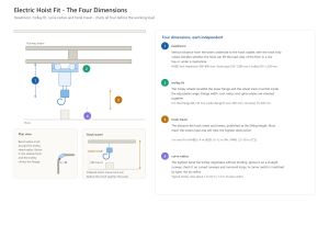
An electric hoist fits a runway only when four dimensions check out: headroom clears the building height, the trolley matches the beam flange, the trolley can take the bends in the track, and the hook travel is long enough to reach the load. Headroom decides whether the load can be lifted clear of the floor at all; trolley fit decides whether the hoist rolls on the existing beam; curve radius decides whether the trolley can take a bend in the runway, and where two runways meet at a corner the switch type has to be matched separately; hook travel decides whether the hook can lower far enough to reach the load. The four are independent: a hoist that clears the height but not the flange cannot be mounted on that beam.
This article covers the four fit dimensions in the order a plant engineer checks them, and it works through the TOYO-INTL chain hoist range, where the same model publishes different headroom figures depending on how it is built and mounted. Where the published TOYO-INTL product page gives a value, that value is cited; where the value is a general industrial range, it is labelled as such and the buyer is directed to the model datasheet.
Key Takeaways
- The TOYO-INTL HHBD chain hoist publishes three headroom figures, one for each of the low-headroom, hook type and trolley-mounted builds, so the model and the mounting style decide the figure as much as the capacity does.
- Trolley fit is the match between the trolley’s adjustable wheel track and the beam flange width; the flange must sit inside that adjustable range.
- Minimum curve radius is the smallest bend the trolley negotiates; a curved runway needs a trolley whose rated radius is below the track bend, and a corner switch is matched by switch type rather than by radius.
- Hook travel is the lifting height on the datasheet; the published TOYO-INTL chain hoist figures are 3 m or 9 m on the HHBD, 4 m on the KDB, 6 to 12 m on the PA and PAW mini hoists and 21 to 30 m on the TCS mini hoist.
- The four fit dimensions are checked before the working load; a hoist that misses any one fails on that runway regardless of capacity.
The Four Dimensions at a Glance
The four dimensions are checked in that order because each one can stop the job on its own: a hoist that meets the height but not the flange cannot be mounted, and a hoist that mounts but cannot take the bend cannot leave the straight. Confirm each figure against the measured runway, and record the datum alongside every number.
What Headroom Means
Headroom is the vertical distance from the underside of the runway beam down to the saddle of the load hook, measured with the hook at its upper limit of travel. It decides whether a hoist can lift its load clear of the floor in a low bay, and on the TOYO-INTL HHBD chain hoist it is published in three figures, one for each build. Two different datums are in use, and the figures they produce differ by roughly 300 to 500 mm, which is the height of the hook block and hook body above the saddle. ASME HST-4M sets the convention used throughout this article: headroom is measured with the load hook at its upper limit of travel, from the saddle of the load hook to the bottom of the beam. Some suppliers publish the smaller figure taken to the top of the hook block instead. Neither number is wrong, but the two are not interchangeable, so ask every supplier to state the datum on the quotation and compare figures only when the basis matches.
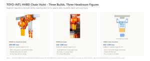
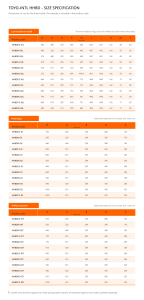
The TOYO-INTL HHBD chain hoist is published in three headroom figures, and the spread between them is the point. The three builds and their dimensions are tabulated below. The three capacity ranges overlap almost completely – 0.5 to 10 t, 0.5 to 7.5 t and 0.5 to 7.5 t – so the spread between the headroom figures comes from the mounting arrangement rather than the capacity. That is why the headroom has to be read from the specific model and the specific mounting style.
The headroom number is published on the model dimension drawing, not in the main spec table. Confirm it against the measured clearance from the beam to the nearest obstruction below, and leave margin for the hook block, the sling and the load — not just the hook at the top.
Trolley fit is the match between the trolley’s adjustable wheel track and the beam flange. An electric trolley runs on two or four wheels that straddle the lower flange of an I-beam or H-beam; the flange width must sit inside the trolley’s adjustable wheel track. A trolley too narrow for the beam cannot seat; a trolley too wide runs off-centre and derates.
The published flange widths cover the common structural sections, but two different products work on that flange and each has its own range. The TOYO-INTL JG beam clamp, used as a rigging point rather than as a running carriage, accepts a 75 to 320 mm I-beam flange width. A trolley is ordered by its adjustable wheel track instead: a unit adjusted to 75 to 200 mm covers most of the standard I12 to I32a population, whose flanges run 68 to 130 mm, while the narrowest I12 section at 68 mm needs a unit that adjusts below 75 mm. Wide-flange H sections carry 300 mm and more, and need a trolley ordered for that width.
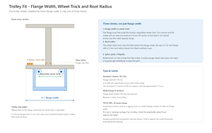
Trolley fit is not only width. The wheel tread must clear the flange root radius, and the trolley wheelbase must clear any gusset, joint cover or fishplate on the runway. Confirm the wheel track, the root clearance and the joint geometry, not the flange width alone. One dimension that gets confused with headroom is hook approach. Headroom is measured vertically, from the underside of the beam down to the hook; hook approach is measured horizontally, from the hook centreline at its furthest working position to a wall or column. It decides how close to the edge of the bay the load can be carried, not how high the hook can rise, so check it against the bay layout rather than against the beam.
Minimum Curve Radius
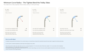
Minimum curve radius is the smallest bend a trolley negotiates without binding. A straight runway ignores it; a curved runway or a monorail loop needs a trolley whose published radius is below the track bend, while a corner switch is chosen by switch type and rail gauge rather than by radius. A trolley pushed through a tighter bend than its rating derates the wheels, twists the frame and can climb the flange.
The published curve radius runs roughly 1.0 to 2.0 m on the common electric trolley class. A two-wheel trolley with a short wheelbase negotiates a tighter bend; a four-wheel trolley with a longer wheelbase needs a wider bend. The number is on the model datasheet, often under a “minimum curve radius” or “minimum turning radius” line. A curved runway designed at 1.5 m radius matches the centre of the class; a tighter 1.0 m curve needs a short-wheelbase trolley, and a 2.0 m or wider curve clears any trolley in the class.
Curve radius interacts with trolley fit. A trolley adjusted wide for an H-beam flange rides closer to the root, and the tighter the bend the more the inner wheel binds. Confirm the radius and the flange together, not the radius alone.
Hook Travel
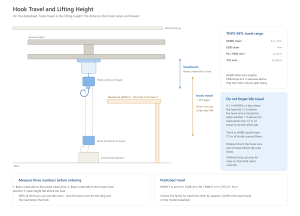
Hook travel is the distance the hook lowers and raises; on a datasheet it is the lifting height. The published figures differ by series, and each series covers a different working height. The HHBD is published at 3 m and 9 m, and the KDB at 4 m, which covers the everyday workshop lifting heights. Above that, the PA and PAW mini hoists run 6 to 12 m, and the TCS mini hoist reaches 21 to 30 m for high-bay work with light loads. The HHBD series that accounts for most chain hoist orders is offered with 3 m and 9 m lifting height options, so travel is a model choice within the family rather than a fixed figure.
Hook travel must reach the lowest load and clear the highest obstacle. Take a hoist with 3 m of lifting height, the shorter of the two HHBD options, in a bay where the load hangs 1.5 m below the hook at its highest position and a mezzanine platform sits 1 m above that load. Reaching the load takes 1.5 m of travel below the hook’s highest position, and clearing the mezzanine takes 1 m of travel back up from there, so the working range stays inside that same 1.5 m: the 3 m HHBD already covers the job, and the 9 m version would leave 7.5 m of stroke unused. A hoist ordered short runs out of travel before the load clears; a hoist ordered long pays for rope or chain that never unwinds.
The published heights follow the same logic across the range. The KDB chain hoist sits at 4 m standard because the load chain column gets heavy above that, and the HHBD offers 3 m and 9 m options; the mini hoists then take over above the workshop range, the PA and PAW from 6 to 12 m and the TCS up to 30 m. Choose the travel first, then the capacity.
How the Four Fit Together
The four dimensions run in order because each gates the next. Headroom decides whether the hoist fits the height; trolley fit decides whether it runs the beam; curve radius decides whether it takes the bend; hook travel decides whether the hook can reach the load. A hoist that clears the height but not the flange never mounts; a hoist that mounts but cannot take the bend never leaves the straight; a hoist that takes the bend but runs short of travel never picks the load up.
The four are checked against the measured runway, not the nominal. A beam stamped 125 mm flange but dressed with a 5 mm root radius and a bolted fishplate needs the trolley that clears the radius and passes the joint. A bay stamped 3.5 m clear but carrying a 200 mm duct across the top gives the hoist 200 mm less room, so the headroom has to be checked against the duct rather than against the beam. The datasheet gives the hoist; the tape measure gives the runway; the fit lives in the match.
Headroom and hook travel pull against each other within the HHBD range. The low-headroom build starts at 400 mm, the tightest figure in the range, while the trolley-mounted build starts at 635 mm; against that, the HHBD is published with lifting heights of 3 m and 9 m. The tighter the ceiling, the more clearly the low-headroom build is the one to specify. Choose the build by headroom first and the travel second, then confirm the trolley and the curve radius against the beam.
RFQ Checklist
- Beam section, flange width and root radius at the runway
- Measured clearance from the underside of the beam down to the lowest obstruction
- Runway geometry: straight, curved or switched, and the bend radius
- Lowest load position and the travel needed to clear the mezzanine
- Hoist build: HHBD low-headroom, hook type or trolley-mounted – and the headroom figure for that build
- Trolley wheel track range and wheelbase, matched to the beam and the joints
- Published headroom (with the measurement datum stated) and minimum curve radius from the model datasheet
FAQ
What is electric hoist headroom?
Headroom is the clear space between the underside of the runway beam and the load hook, measured with the hook at its upper limit of travel. The TOYO-INTL HHBD publishes one figure per build: 400 to 890 mm for the low-headroom build, 530 to 1,380 mm for the hook type and 635 to 1,200 mm for the trolley-mounted build. Some suppliers publish the smaller figure taken to the top of the hook block instead, a difference of roughly 300 to 500 mm, so state the datum on the quotation and compare figures only when the basis matches.
How do I match an electric hoist trolley to a beam?
Match the trolley wheel track to the beam flange width, and check that the wheel tread clears the flange root radius. The TOYO-INTL JG beam clamp accepts a 75 to 320 mm I-beam flange width; for a trolley, check its own adjustable wheel track against the beam instead. Confirm the flange width, the root radius and any joint fishplate on the runway.
What is the minimum curve radius on a hoist trolley?
The minimum curve radius is the smallest bend a trolley negotiates without binding. The common electric trolley class rates roughly 1.0 to 2.0 m. A runway designed at 1.5 m radius matches the centre of the class; a tighter bend needs a short-wheelbase trolley.
Is hook travel the same as lifting height?
Yes, and both are different from headroom. Hook travel is the distance the hook raises and lowers; on a datasheet it is the lifting height, measured from the lowest working position of the hook to its highest. The published TOYO-INTL chain hoist figures are 3 m or 9 m on the HHBD and 4 m on the KDB, with the PA and PAW mini hoists at 6 to 12 m and the TCS mini hoist at 21 to 30 m.
Why does the same chain hoist publish three different headroom figures?
Because the headroom depends on how the hoist is built and how it is mounted, not on the capacity alone. The low-headroom build sets the motor and gearbox beside the beam so the hook can be brought close to it; the hook type hangs from a fixed upper hook with no runway below it; the trolley-mounted build adds the trolley frame between the beam and the hoist body. Quote the build you need and the figure for that build, and compare it only against figures quoted on the same basis.
Conclusion
Headroom, trolley fit, curve radius and hook travel are the four fit dimensions that decide whether an electric hoist mounts and runs on a given runway. Headroom clears the height; trolley fit runs the beam; curve radius takes the bend; hook travel lowers the hook to the load. Check the four against the measured runway before the working load, because a hoist that misses any one fails regardless of capacity. Choose the build by headroom and travel first, then confirm the trolley and the radius against the beam and the bend.
To confirm the published headroom, the trolley track range and the minimum curve radius for a specific model, [quote the beam section, the bend radius and the travel needed](https://www.toyointl.com/product-category/electric-hoist/) so the supplier matches the hoist to the runway.